ILS (Instrument Landing System) is a system of radio devices used by aircrafts flying in a non-visual meteorological conditions when on the final part of the landing. This system helps pilots to navigate their airplanes towards the runway equipped with ILS.
The ILS consists of two electronic beams (i.e. transmitters which transmit highly directional radio emissions): one provides horizontal guidance (the so-called localizer); the other, vertical guidance (the so-called glideslope). In addition to these beams, a DME device is usually placed at the runway threshold. Moreover, two (or three) marker beacons are normally used, which provide additional information about distance from runway threshold.
The localizer transmitter emits a radio beam in direction of runway centerline. The glidepath transmitter emits a radio beam in the same direction, but the beam is elevated at a glidepath angle from ground (usually 3°). The DME provides precise distance information from the runway threshold. The marker beacons are antenna arrays which emit a vertical beam to indicate the pilot that his airplane is at a specific point. Ordinarily, there are two marker beacons associated with an ILS, the OM (Outer Marker) and MM (Middle Marker). Locations with a Category II and III ILS also have an Inner Marker (IM). When an aircraft passes over a marker, a light will light in the cabin and pilot will hear a specific sound pattern:
| Marker | Sound code | Light |
| OM | – – – | Blue |
| MM | . – . – | Amber |
| IM | . . . . | White |
When pilot wants to use ILS, he tunes its localizer frequency on the primary NAV receiver. The glideslope frequency is fixedly paired with the localizer frequency, so it is tuned automatically. Both needles on the HSI now display the deviation of the aircraft from the extended runway centerline and glideslope. The DME receiver displays distance to the runway threshold. Pilot should fly "towards the needles" to position the airplane on the best approach path. The marker beacons have fixed frequencies, so the pilot does not tune them at all. (Moreover, it often happens that aircraft receives marker beacon's signal in another phase of flight, when by chance overflying some marker beacon.)

|
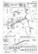
Here is an example of an approach chart for an ILS-equipped runway. The chart contains all required frequencies, courses and other information required for ILS approach. |
Using this applet you can try what a pilot sees on an ILS approach. Press arrow keys to turn the airplane, press space to move the airplane a bit forward. Try to navigate the airplane to the runway.
You can also click with a left mouse button on the upper map to position the airplane, or click with the right mouse button to turn the airplane towards the selected point. On the lower map, you can click with the left button to change the altitude of the airplane, or with the right button to turn the airplane's nose up or down.
The instruments at the bottom are (from the left):
If you do not see the applet, either your browser does not support applets at all, or you have disabled Java, or you have old Java version in your browser (the applet requires Java 2 to run). You may try to download new version of Java from Sun.